Revealed

A blog about scientific and medical visualization and all that’s involved.

Archive for the ‘my projects’ Category

3D Lamp Contest Poll

Posted by Janet on September 18, 2009

Here is the lamp shade I designed for the 3D Print Lamp Contest hosted by i.materialize for Blender artists:

cchao1-GFP-LampHope this appeals to the science illustrators and anyone else who’s likes proteins, jellyfish, or anything that lights up 😉 Please correct me if you catch any mistakes, it was getting late…

To vote for your favorite lamp design (and please do, the top 3 winners get their design fabricated and delivered), follow these steps:

1. View all the designs here.

2. Register with the Blender Artists Forum at http://blenderartists.org/forum/register.php if you haven’t already. Sign in.

3. Vote for your favorite design here. Only one design per voter.

Posted in announcements, digital 2D/3D, my projects | Tagged: , , | 3 Comments »

Modeling Lung Anatomy

Posted by Janet on August 8, 2009

*3ds Max lung model © Denoyer-Geppert, images used with permission.

Following “Visualizing Lung Anatomy,” I can now begin to model the lung. First, I took screen shots of the lung in VolView in three orthographic views–top, left, and front. Then I set up three orthographic planes and added each image as materials to the planes. I prefer this method over using a background image because this allows you to see the images in perspective views as you rotate objects. You also don’t have to worry about shifting your objects and locking zoom, which in my version of 3ds Max gets a little quirky.

LungModel1

Next, I put more planes in the scene, took a screen shot of every twentieth slice from the data set, and applied the screen shots to the planes as materials. Now that I have slices of the lung from front to back, I outlined each slice in the front viewport. Notice that the outlines are all located on the same plane. This will be fixed later. (If you are wondering why the “right” lung is on the left side, it’s because the “person” is facing us so their right is our left.)

LungModel2LungModel3LungModel4

Once the outlines are complete, I calculated the distance I must offset each line in order for it to fit the profiles correctly. After the outlines are moved to their correct positions, you can clearly see the shape of a lung in the perspective view. The lines must be linked together in order for a surface to be created. I selected one outline and used the “Attach Multiple” option under the modify panel. For now, I keep the front and back halves separate so I can easily hide the back side when necessary. Then, using the “Connect” and “Refine” features under the modify panel, I connected vertices between the outlines.

LungModel5

Here is what the model looks like with connections between the outlines:

LungModel6

Using the “Surface” modifier, I created a surface using this mesh. At this point it’s not perfect. I must go back and adjust the mesh until the entire surface can be covered:

LungModel7

A model of the lung without holes in the model:

LungModel8

The lung is looking nearly perfect, but overall still appears rough. Adding “Relax” and “TurboSmooth” modifiers will help refine the mesh:

LungModel9

This is one way to make a model of the human lung. I chose this method because I wanted to capture the accuracy in shape and had tools to visualize CT scan data. I also chose not to model the lobes separately because they are not the primary concern for this project and can be added later using materials.

Posted in anatomy, digital 2D/3D, my projects, techniques | Tagged: , , , , | 2 Comments »

Visualizing Lung Anatomy

Posted by Janet on July 27, 2009

One of the projects I’m currently working on at home involves building a 3D model of the right lung. To make sure the model will be as accurate as possible in terms of shape, I would need to know the lung anatomy before I begin building the model.

The first thing I did was going to a library to look at drawings and photographs of lungs. I did a few quick sketches and wrote down some notes on how I will approach this in a 3D program:

sketch1sketch2
Now comes the fun part…

Next, I went to CVS and bought some Crayola modeling clay and began to build a small lung model while looking at online images of the lung. I tried to find as many variations in as many angles as possible, but most resources only showed the standard views. The e-anatomy website very helpful for this initial step, since it provides cross sectional images, labels of structures, and several different ways of presenting the structures. (The website is free, but registration is required to gain full access to the labels and features. High res images and full screen mode are available with a fee, but for our purpose this isn’t necessary.)

The purpose of making a clay model is to get a concrete physical sense of the three-dimensional shape. I find this step very important because it forces you to piece together two-dimensional visuals into a three-dimensional object. It is through this process that I begin to realize the complexity of the shape of a lung.

Below: Clay lung, heart, and a piece of unused clay.

clay-lung

To begin the digital visualization process, I looked further to find visualization tools that would allow me to use actual human data, look at the structures from various angles, and isolate unnecessary structures. Osirix, an open source DICOM viewer, is perfect for the job. It even has data sets available for download. The only problem is…Osirix is Macs only, and I only have access to PCs.

After poking around for a while, I found a similar product called VolView that works on a PC. VolView comes with a $1000 yearly or a $2500 unlimited licencing fee, but it has a 30 day free trial for download. I was able to import a data set from the Osirix website into VolView. My impression of VolView after two days is that it is very easy to navigate, comes with instructions (Help –> Help Topics), gives good results, and has powerful features. One thing I haven’t figured out is whether there is a cut feather that allows the user to trim away unnecessary parts. There seems to be a segmentation tool under the “Analysis” tab, but the instructions for this feature is limited and it is a feature that does not allow “undo.” That is scary. The first time I tried it, it messed up a model I had been playing with for two hours, but it warns you first so you feel like it’s your own fault for not listening. Luckily I was able to reproduce the same result ten minutes later. Here is a screen shot of my lung visualization:

volview-lung
…and a detailed shot of the lung. You can see the bronchi entering the right lung, but notice there are still some artifacts on the side.
volview-lung-detail

*See “Modeling Lung Anatomy” for the next step in this process.

Posted in anatomy, digital 2D/3D, my projects, photography/imaging, techniques | Tagged: , , , , | 4 Comments »

Random Thoughts; Book Chapter and Working with Engineers

Posted by Janet on May 17, 2009

I’m not really sure how things get done. I’d say right now I’m in limbo–having finished taking classes but not yet fulfilled all graduation requirements. Still three more days of internship left before leaving for semi-vacation, and all this time while trying to pack, see friends, and work on a side illustration project. A week after returning, I’ll be packing again to go to another internship, this time to the other side of the country.

This illustration project I’m working on is part of a to-be-published book chapter. All the illustrations are diagrammatic, and for the most part they are already drawn. My job is simply to increase readability and make sure everything fits the publication requirements. Unfortunately, the images did not contain layers so the simple changes involve retracing a large portion of the original image. I’m also learning more than I expected to about working with engineers’ conventions.

Unlike illustrators, most engineers use different software to produce diagrams. The reasons are completely valid, but sometimes that makes it more difficult for illustrators to make all the necessary changes quickly. While designers would most likely format text through InDesign, for this project I was presented with a LaTeX document. This resulted in a day spent uninstalling an old version of MikTeX that somehow made its way to my laptop years ago, downloading and installing the newer version, and figuring out how to compile.

Other challenges include gaining some knowledge about the subject matter you’re working with. While it’s not necessary to know all the details of what’s going on in the paper, it helps to have at least a general idea in order to make suggestions to the client on ways to convey the information better via graphics. I felt abonormally proud of myself when I caught a small error in the original diagram, and again when my client decided to trust me completely to convert the units on his graphs.

Perhaps the most overwhelming part of this project is the sheer number of diagrams that needs to be redrawn. In less than three weeks I’ve retraced and reformatted nearly fifty diagrams. Although not the most difficult, it is the largest number of pages per client I have worked with so far. I’ve heard from more experienced illustrators that a book deal is the way for illustrators to become extremely skilled at a certain media. Books usually require a consistent style. With enough diagrams to keep you busy for months, it’s not surprising that people can crank out illustrations pretty quickly near the end.

It’s time to go back to the diagrams, or maybe just pack a little more and sleep. Vacation is calling.

Posted in business, my projects | Leave a Comment »

Skull Cleaning

Posted by Janet on May 10, 2009

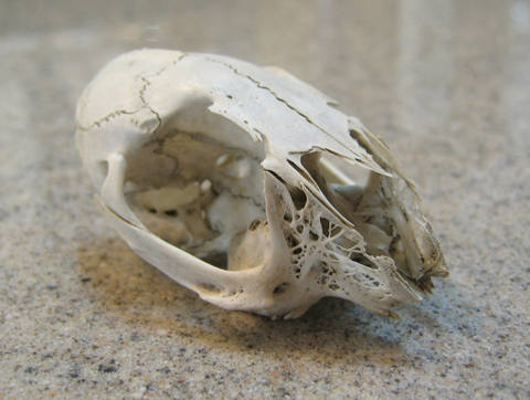
On a recent volunteer trip to a state park, one of the other volunteers found a skull in the bushes. I decided to bring it home and add it to the collection. There was nothing to put it in except a used sandwich bag. When I took it out in the evening, it was covered with dirt from the ground and oil spots from the sandwich bag.

First, I wanted to sterilize the skull and get rid of large debris. I decided that boiling the skull was the quickest method. I had read about forensic anthropologists boiling parts to get rid of the muscle tissues, but was still a bit nervous about doing it. The image below shows the skull in a small stainless steel pot (part of a cookware set for children from IKEA, also very useful for small non-food projects)

skull1

Above: Dirty and oil-stained skull and a bone; Below: Skull in a pot for boiling.

skull2

Below: The skull is coming to a full boil. It’s NOT falling apart…it’s actually working. Yay.

skull3

After boiling and getting rid of larger debris, I left the skull in the water for an hour to cool. Then I drained the water, rinsed it a couple times, and filled the pot with hydrogen peroxide to cover the skull. After about a day, it removed the smaller debris and some of the coloration. Honestly, the result wasn’t as dramatic as I expected, but it did a good job. Overall, no damages except a tooth fell out, but I think it was going to fall out anyway.

Below: The nice, clean skull after boiling and a day of hydrogen peroxide treatment.

skull4

Posted in miscellaneous, my projects | Tagged: , , , | 1 Comment »

Anatomical Model Internship–Part 2

Posted by Janet on March 19, 2009

(Continued from part 1)

A while ago I encountered an episode of “How It’s Made” on the Discovery Channel that showed the process of making anatomical models. If you have seen that episode, that sums up how these models are made in a nutshell. The process begins with a design. A prototype is created from the design. From the prototype, a metal mold is made and this mold is then used and reused many times to produce the anatomical models. The models are then trimmed, painted, and assembled. Even though this is considered “mass production,” the entire process is time consuming and requires a lot of “hand made” procedures. This is why anatomical models can be very expensive.

When a design is completely new, the model needs to be sculpted by hand. However, sometimes the anatomical model company already owns a model that is similar to the new design. If such is the case, the original model can be scanned with a 3D scanner and edited using a computer software. The final file is sent to a rapid prototyping machine, where a prototype is created. Some companies own their own rapid prototyping machines. Those who don’t usually send their designs to rapid prototyping service bureaus. This newly created raw model is rarely perfect. To complete the process, a sculptor must smooth the piece and re-carve the fine details.

The next step is mold creation. Metal is chosen for their heat tolerance and durability. The mold design can be tricky because anatomy often have very complicated shapes. In order to avoid undercuts, the design of both the model and the mold needs to be carefully considered. Like the previous process, the mold can also be created off site by another company.

Once the mold is made, a worker fills the mold with materials and churns it so the material fills the entire mold surface. The raw model is removed while still warm and left to cool. During the cooling process, the material shrinks slightly, contributing to the difficulty of fitting multiple parts together in a precise manner. The edges of each model are trimmed, and the models line up on shelves waiting for the next step. Eventually some models are sprayed with a base paint. Sometimes the base color is the color of the material, so the layer of paint isn’t always necessary. Painters then take the models and hand paint them according to a chart to ensure accuracy in all the models. The paint used in this process forms a chemical bond with the material, preventing the paint from being rubbed off easily. Finally, assemblers drill holes and fit the different parts of a model together.

Posted in business, my projects, stores/products | 2 Comments »

Anatomical Model Internship–Part 1

Posted by Janet on March 13, 2009

I would really like to share some things that I’ve been doing at my internship, but since the projects are manufactured into products, I can’t actually talk about it until the products come out. Instead, I will talk a little bit about the company, the manufacturing process, and give some tips for finding internships.

Denoyer-Geppert is an anatomical model company based in Skokie. It is a manufacturer as well as a distributor, which means that the company makes its own models as well as buys models from other companies to sell. In addition to making models, Denoyer-Geppert also produces illustrations. These illustrations can be a stand alone product, but they are often part of an educational package or used to compliment a model.

Most of the time, designers or freelancers (which is technically what I am) at the company design products and produce illustrations, and the company owns all rights to the work. Yes, this means that you can’t show your own work freely on your website without the company’s permission. You even have to be careful NOT to make derivative works from something you created at a company. Occasionally, an outside scientist, educator, artist, or anyone would have an idea for a model they would like the company to manufacture. So they will call the company and negotiate a deal. If this is the case, the creator of the model is credited and/or may enjoy certain benefits when the models sell. Examples of such models include “Plane Jane,” a model showing the anatomical planes, and the “Complete Sarcomere Model,” which illustrates the sliding filament theory.

Stay tuned for part 2 about the design and manufacturing process.

plane-jane sarcomere
Above Left (Top): Plane Jane; Above Right (Bottom): Complete Sarcomere Model

Posted in business, my projects, stores/products | 1 Comment »

Website Updated

Posted by Janet on January 31, 2009

Check it out–my updated portfolio website with improved appearance and a selection of the latest works. http://www.illustrationideas.com/

Posted in announcements, my projects | Leave a Comment »

The Making of an Eye

Posted by Janet on July 21, 2008

If you have seen my posts about the prosthetic ear, I am now taking a continuation of that course this summer. For two classes we made a prosthetic eye. Since summer classes are typically accelerated, we focused on materials and techniques for making the eye and left out any patient-specific parts of the process for the next class. Read on for a summary of this process.

First my instructor demonstrated painting the iris. Here he is attaching an ocular button (the transparent half-sphere with a peg on one end) to an ocular disc, the surface on which we paint iris patterns.

Holding onto the peg of the ocular button, the iris is painted onto the disc.

Later the ocular button is removed (from the back side) and another one is glued to the front side. We used an existing prosthetic eye to make a mold since we were not working from patients. Typically a cast would have to be made from a patient’s eye and the mold would be made from this cast.
From Right to Left: painted ocular disc, ocular disc with ocular button attached to the front, and an existing eye from which we will make a mold.

The mold is covered in tin foil to prevent moisture from contaminating the materials. The ocular button with painted disc (middle in above picture) is placed into the mold, with the peg inserted into the hole in the mold so it would stay in place. White acrylic is prepared and placed into the mold. The mold is then pressed tight and placed in a heat curing unit.

This is what the eye looks like when removed from the mold. It was sanded down until smooth and that the clear part of the ocular button is once again visible. The sclera was tinted slightly and blood vessels added. The eye was then placed back into the mold with clear acrylic covering the front side this time.

Once the acrylic cures, the eye was removed from the mold. The rough edges were sanded away and the entire eye was polished to a high shine.

Posted in my projects, prosthesis | Tagged: | Leave a Comment »

Ear Prosthesis Part 5 (final)

Posted by Janet on May 19, 2008

I know it’s been a long time since my last post with the prosthesis. There were some major changes with the project schedule, but I finally finished the last part–the extrinsic coloring.

We started by visually analyzing the prosthetic ear from the last step to see how the colors match up with the patient’s skin. Then we decide which colors to apply for a better color match. In my case, the ear came out of the intrinsic coloring process a little too green and yellow, so I will apply various shades of red to even out the tone and bring the ear back to life.

The materials: color pigments and silicone (a different type from the ones used for the intrinsic part of the ear).

extrinsic-materials

I put some pigments on a piece of palette paper and some silicone in a cup. Then I gradually mixed the pigments with silicone using a blunt brush until I got the desired color. The colors can be painted or stippled onto the ear. I found that when I stippled the colors, they tend to stick to parts of the ear in clumps. I actually preferred applying the colors onto the general section and then buffing the colors away using a piece of gauze to create a more subtle transition between the layers. Sometimes buffing the colors can make the ear too glossy, so I’ll reapply some texture by dabbing the ear using a textured surface.

extrinsic-painting

Below: the prosthetic ear completed with extrinsic coloring.

ear-prosthesis

Posted in my projects, prosthesis | Tagged: , , | 1 Comment »